- 您现在的位置:买卖IC网 > Sheet目录3850 > PIC18F86J11-I/PT (Microchip Technology)IC PIC MCU FLASH 32KX16 80TQFP
PIC18F87J11 FAMILY
DS39778E-page 60
2007-2012 Microchip Technology Inc.
5.7
Reset State of Registers
Most registers are unaffected by a Reset. Their status
is unknown on POR and unchanged by all other
Resets. The other registers are forced to a “Reset
state” depending on the type of Reset that occurred.
Most registers are not affected by a WDT wake-up,
since this is viewed as the resumption of normal
operation. Status bits from the RCON register (CM, RI,
TO, PD, POR and BOR) are set or cleared differently in
different Reset situations, as indicated in Table 5-2.
These bits are used in software to determine the nature
of the Reset.
Table 5-3 describes the Reset states for all of the
Special Function Registers (SFRs). These are
categorized by Power-on and Brown-out Resets,
Master Clear and WDT Resets, and WDT wake-ups.
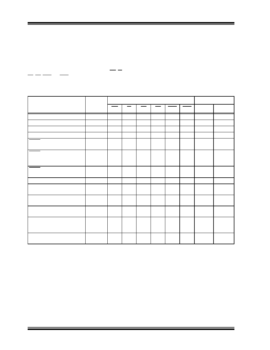
TABLE 5-2:
STATUS BITS, THEIR SIGNIFICANCE AND THE INITIALIZATION CONDITION FOR
RCON REGISTER
Condition
Program
Counter(1)
RCON Register
STKPTR Register
CM
RI
TO
PD
POR
BOR
STKFUL
STKUNF
Power-on Reset
0000h
11
0
RESET
instruction
0000h
u0
uu
u
Brown-out Reset
0000h
11
u
0
u
Configuration Mismatch Reset
0000h
0u
uu
u
MCLR Reset during
power-managed Run modes
0000h
uu
1u
u
MCLR Reset during
power-managed Idle modes
and Sleep mode
0000h
uu
10
u
MCLR Reset during full-power
execution
0000h
uu
u
Stack Full Reset (STVREN = 1)
0000h
uu
u
1
u
Stack Underflow Reset
(STVREN = 1)
0000h
uu
u
1
Stack Underflow Error (not an
actual Reset, STVREN = 0)
0000h
uu
u
1
WDT time-out during full-power
or power-managed Run modes
0000h
uu
0u
u
WDT time-out during
power-managed Idle or Sleep
modes
PC + 2
uu
00
u
Interrupt exit from
power-managed modes
PC + 2
uu
u0
u
Legend: u
= unchanged
Note 1:
When the wake-up is due to an interrupt and the GIEH or GIEL bit is set, the PC is loaded with the interrupt
vector (0008h or 0018h).
发布紧急采购,3分钟左右您将得到回复。
相关PDF资料
PIC18F66J50-I/PT
IC PIC MCU FLASH 32KX16 64TQFP
PIC24FJ96GA006-I/PT
IC PIC MCU FLASH 96KB 64TQFP
PIC18F4321-I/ML
IC PIC MCU FLASH 4KX16 44QFN
PIC24FJ32GB002-I/SP
IC MCU 16BIT 32KB FLASH 28DIP
DSPIC33FJ16GP304-I/PT
IC DSPIC MCU/DSP 16K 44TQFP
PIC16C62B-20I/SP
IC MCU OTP 2KX14 PWM 28DIP
DSPIC30F2010-20I/SP
IC DSPIC MCU/DSP 12K 28DIP
AT89S52-24AC
IC MCU 8K FLASH 24MHZ 44-TQFP
相关代理商/技术参数
PIC18F86J11T-I/PT
功能描述:8位微控制器 -MCU 64KB Flash 3936bytes RAM 67 I/O RoHS:否 制造商:Silicon Labs 核心:8051 处理器系列:C8051F39x 数据总线宽度:8 bit 最大时钟频率:50 MHz 程序存储器大小:16 KB 数据 RAM 大小:1 KB 片上 ADC:Yes 工作电源电压:1.8 V to 3.6 V 工作温度范围:- 40 C to + 105 C 封装 / 箱体:QFN-20 安装风格:SMD/SMT
PIC18F86J15-I/PT
功能描述:8位微控制器 -MCU 96 KB FL 4 KB RAM RoHS:否 制造商:Silicon Labs 核心:8051 处理器系列:C8051F39x 数据总线宽度:8 bit 最大时钟频率:50 MHz 程序存储器大小:16 KB 数据 RAM 大小:1 KB 片上 ADC:Yes 工作电源电压:1.8 V to 3.6 V 工作温度范围:- 40 C to + 105 C 封装 / 箱体:QFN-20 安装风格:SMD/SMT
PIC18F86J15T-I/PT
功能描述:8位微控制器 -MCU 96 KB FL 4 KB RAM RoHS:否 制造商:Silicon Labs 核心:8051 处理器系列:C8051F39x 数据总线宽度:8 bit 最大时钟频率:50 MHz 程序存储器大小:16 KB 数据 RAM 大小:1 KB 片上 ADC:Yes 工作电源电压:1.8 V to 3.6 V 工作温度范围:- 40 C to + 105 C 封装 / 箱体:QFN-20 安装风格:SMD/SMT
PIC18F86J16-I/PT
功能描述:8位微控制器 -MCU 96KB FL 3936b RAM 10 MIPS 67 I/O RoHS:否 制造商:Silicon Labs 核心:8051 处理器系列:C8051F39x 数据总线宽度:8 bit 最大时钟频率:50 MHz 程序存储器大小:16 KB 数据 RAM 大小:1 KB 片上 ADC:Yes 工作电源电压:1.8 V to 3.6 V 工作温度范围:- 40 C to + 105 C 封装 / 箱体:QFN-20 安装风格:SMD/SMT
PIC18F86J16T-I/PT
功能描述:8位微控制器 -MCU 96KB Flash 3936bytes RAM 67 I/O RoHS:否 制造商:Silicon Labs 核心:8051 处理器系列:C8051F39x 数据总线宽度:8 bit 最大时钟频率:50 MHz 程序存储器大小:16 KB 数据 RAM 大小:1 KB 片上 ADC:Yes 工作电源电压:1.8 V to 3.6 V 工作温度范围:- 40 C to + 105 C 封装 / 箱体:QFN-20 安装风格:SMD/SMT
PIC18F86J50-I/PT
功能描述:8位微控制器 -MCU 64KB Flash 3936byte RAM RoHS:否 制造商:Silicon Labs 核心:8051 处理器系列:C8051F39x 数据总线宽度:8 bit 最大时钟频率:50 MHz 程序存储器大小:16 KB 数据 RAM 大小:1 KB 片上 ADC:Yes 工作电源电压:1.8 V to 3.6 V 工作温度范围:- 40 C to + 105 C 封装 / 箱体:QFN-20 安装风格:SMD/SMT
PIC18F86J50T-I/PT
功能描述:8位微控制器 -MCU 64KB FLSH 3936Bs RAM USB 2.0 nanoWatt RoHS:否 制造商:Silicon Labs 核心:8051 处理器系列:C8051F39x 数据总线宽度:8 bit 最大时钟频率:50 MHz 程序存储器大小:16 KB 数据 RAM 大小:1 KB 片上 ADC:Yes 工作电源电压:1.8 V to 3.6 V 工作温度范围:- 40 C to + 105 C 封装 / 箱体:QFN-20 安装风格:SMD/SMT
PIC18F86J55-I/PT
功能描述:8位微控制器 -MCU 96KB FLSH 3936Bs RAM USB 2.0 nanoWatt RoHS:否 制造商:Silicon Labs 核心:8051 处理器系列:C8051F39x 数据总线宽度:8 bit 最大时钟频率:50 MHz 程序存储器大小:16 KB 数据 RAM 大小:1 KB 片上 ADC:Yes 工作电源电压:1.8 V to 3.6 V 工作温度范围:- 40 C to + 105 C 封装 / 箱体:QFN-20 安装风格:SMD/SMT